


ScreenShots:


Software Description:
Dlubal PLATE-BUCKLING is a separate stand‑aloneprogram which performs plate buckling analysis of rectangularplates according to the EN 1993‑1‑5:2006 and DIN 18800‑3:1990‑11standards. It is possible to apply horizontal or verticalstiffeners to the plates (for example flat plates, angles,T‑stiffeners, trapezoidal stiffeners, channel sections). Loading onthe plate boundaries can be applied in several ways and can beimported from the main program RFEM/RSTAB. The plate bucklingdesign in RF‑/PLATE‑BUCKLING is always performed on the totalbuckling panel as the potential stiffeners are considered in the 3DFE model. Thus, designs of single (c/t) parts or buckling panelsections are omitted.
Features:
For design according to Eurocode 3, the following National Annexes(NA) are available:
– Belgium NBN EN 1993-1-5/NA:2011-03 (Belgium)
– Cyprus CYS EN 1993-1-5/NA:2009-03 (Cyprus)
– CSN EN 1993-1-5/NA:2008-07 (Czech Republic)
– SFS EN 1993-1-5/NA:2006 (Finland)
– DIN EN 1993-1-5/NA:2010-12 (Germany)
– UNI EN 1993-1-5/NA:2011-02 (Italy)
– NEN EN 1993-1-5/NA:2011-04 (Netherlands)
– NS EN 1993-1-5/NA:2009-06 (Norway)
In addition to the National Annexes listed above, you can alsodefine a specific NA, applying user-defined limit values andparameters.
– Import of all relevant internal forces from RFEM/RSTAB byselecting numbers of members and buckling panels with determinationof governing boundary stresses
– Summary of stresses in load cases with determination of governingload
– Separate materials for stiffener and plate
– Import of stiffeners from an extensive library (flat plate andbulb flat steel, angle, T-section, channel, and trapezoidalsheeting)
– Determination of effective widths according to EN 1993-1-5 (Table4.1 or 4.2) or DIN 18800, Part 3, Eq. (4)
– Optional calculation of critical local buckling stresses byanalytical formulas of annexes A.1, A.2, A.3 of EC 3 or by means ofFEA calculation
– Designs (stress, deformation, torsional buckling) of longitudinaland transverse stiffeners
– Optional consideration of buckling effects according to DIN18800, Part 3, Eq. (13)
– Photo-realistic representation (3D rendering) of buckling panelincluding stiffeners, stress conditions, and buckling modes withanimation
– Documentation of all input data and results in a verifiableprintout report
Input
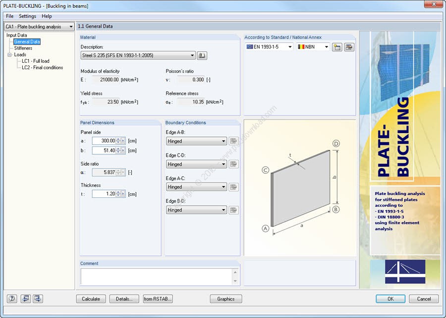
Initially, it is necessary to define material data, paneldimensions, and boundary conditions (hinged, built-in, unsupported,hinged-elastic). It is possible to transfer the data fromRFEM/RSTAB. Then, boundary stresses can be either defined for eachload case manually or imported from RFEM/RSTAB.
Stiffeners are modeled as spatially effective surface elements thatare eccentrically connected to the plate. Therefore, it is notnecessary to consider the stiffener eccentricities by effectivewidths. The bending, shear, strain, and St. Venant stiffness ofstiffeners as well as the Bredt stiffness of closed stiffeners isdetermined automatically in a 3D model.
Design
Designs are performed in iterative steps by eigenvalue calculationof the ideal buckling values for the individual stress conditionsas well as of the buckling value for the simultaneous effects ofall stress components.
The buckling analysis is based on the method of reduced stresses,comparing the acting stresses with a limit stress condition reducedfrom the yield condition of von Mises for each buckling panel. Thedesign is based on a single global slenderness ratio determined bythe entire stress field. Therefore, the analysis of single loadingand subsequent merging using interaction criterion is omitted.
In order to determine the plate buckling behavior, which is similarto the behavior of a buckling member, the module calculateseigenvalues of the ideal panel buckling values using freely assumedlongitudinal edges. Then, slenderness ratios and reduction factorsare determined according to EN 1993-1-5, Chapter 4 or Annex B, orDIN 18800, Part 3, Table 1. Finally, the analysis is performed inaccordance with EN 1993-1-5, Chapter 10, or DIN 18800, Part 3, Eq.(9), (10) or (14). The buckling panel is discretized in finitequadrilateral or, if necessary, triangular elements. Each elementnode has six degrees of freedom.
The bending component of a triangular element is based on theLYNN-DHILLON element (2nd Conf. Matrix Meth. JAPAN – USA, Tokyo)according to the bending theory of Mindlin. However, the membranecomponent is based on the BERGAN-FELIPPA element. The quadrilateralelements consist of four triangular elements while the inner nodeis eliminated.
Results
Results are displayed with references to EN 1993-1-5 or DIN 18800.In addition, RF-/PLATE-BUCKLING shows calculation resultsseparately for the action of only one edge load as well as for thesimultaneous effect of all edge loads. In the case of several loadcases, the governing load case is displayed separately. Thus, atime-consuming comparison of calculation data is not necessary.
You can visualize the buckling modes and loads of buckling panel inthe graphic window in order to facilitate a quick overview. Usingthe animation option, you can clearly represent the bucklingbehavior of stiffened plates. Finally, it is possible to export alltables to MS Excel or OpenOffice.org Calc or in a CSV file.
Installer Size: 530 MB
Download Links : Dlubal PLATE-BUCKLING v8.06.1103 x64 + Crack