


ScreenShots:
Software Description:
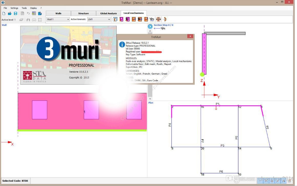
3Muri is a software for analysis of structuresbuilt in masonry and mixed materials through a non-linear(pushover) and static analysis. The strengths of 3Muri is itsinnovative computation method (FME) that is able to give moreinformation on the structure’s real behaviour to seismic actions,aside an extreme simplicity of use.
3Muri offers a drawing area for insertion of the structure withintuitive controls, an engine for the creation of computationmodels and their solutions, and a post-processor for immediatepresentation of the results and creation of the computationreport.
3Muri offers a drawing area for insertion of the structure withintuitive controls, an engine for the creation of computationmodels and their solutions, and a post-processor for immediatepresentation of the results and creation of the computationreport.
3Muri was created by a joint project of S.T.A. DATA and theresearch group headed by Professor Sergio Lagomarsino, from theConstruction Technique department of Genova University. Along withother specialists (eng. Andrea Penna and eng. Alessandro Galascofrom Pavia’s Eucentre, and eng. Serena Cattari, Genova University)they finalized the theoretical aspects of 3Muri throughlaboratory’s experiments and analysis on real structures. Thatcontinuous collaboration guarantee an always updated software,completely operative and reliable for the most professionalrequirement.
Sensitivity Analysis
Sensitivity Analysis is a calculation method aimed to obtain betterunderstanding of the structural functioning and accurate planningof the site investigation plan. As known, doubts during modelingdirectly affect the evaluation of seismic safety. A specificexample is materials mechanical properties, usually defined on thebasis of reference values and for which, through investigation, itaims to limit the inescapable uncertainty. Since the site testshave frequently high economic cost, the possibility to identify inadvance (through the Sensitivity analysis) significant testingcampaign points can limit investigation costs which result mightnot be of interest.
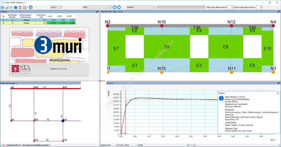
Overlapping capacity curves
This feature allows the designer to simultaneously refer to thecapacity curves of more analysis on a single diagram.
3D modeling
To the current input in (2d) plan was joined a (3D) axonometricinput mode, with the following characteristics. You can insert thestructural objects directly in an axonometric view.
3D modeling is not developed only with the aim to provide analternative to the already existing plan input but also provide anew mode of already allocated structures editing. Currently theelements properties multiple editing is easy in plan but lessperforming in elevation. The editing in 3D will simultaneouslychange the characteristics of the elements at different levels.
Specific applications of 3D editing
Following a multiple selection of structural objects (also ondifferent levels), you can:
Align panels
It performs the concurrent editing of masonry walls with differentthicknesses at different levels in order to align them with thesame outer edge. This operation, that so far was carried out byplacing in the wall properties the eccentricity value to bemanually calculated, is now fully automated.
Assign wind exposed
The properties of a wind exposed panel can be assigned through amultiple selection.
Table editing
The editable table elements has always shown the characteristics ofall the model’s elements.
3D Filters-The Parts
Allows to transform groups of structural elements in defined parts.Working with parts makes easier the simultaneous editing phases ofmultiple elements. You can display one or more parts, called activeparts, at once.
There are two types of parts: user defined parts and logical parts.The user defined parts are created by the user selecting the itemsthat belong to the parties.
The logical parts are automatically created by the program,ordering the items in different criteria categories (material,elements).
Automatic detection of the thickness
During the input phase, you no longer have to worry about thevarious wall thickness in the different sections and perform theinput with any thickness. In a second step a dedicated command (bytracing a segment that intersects the wall) automaticallycalculates the thickness by extracting it from the DXF file andassigns it to the already defined section.
Input by dimension lines
The input of the walls without the DXF background and without theneed to use a coordinates box is possible through the caddimensioning command with ability to directly enter the extensionof the wall. The direction of the walls can be easily identifiedthrough the use of guidelines. The same dimensioning command isavailable for moving nodes, openings and concentrated loads.
IFC management – Output/Input
Export 3Muri to IFC Once you have finished creating the model, thecommand “IFC export” in the File menu allows to create the IFCfile. This file includes the structural objects defined by the IFCstandard in order to be visible with a player or BIM CAD.
Advanced importation
Runs the OpenCAD application, a CAD system that makesinteroperability its strong point. With interoperability we meanthe ability to cooperate and exchange information with the otherproducts or services with resources’s optimization. The informationexchange takes place through various graphic formats: IFC, DGN(Bentley), DXF, SKP (File Sketchup), EMF, WMF, BMP, GIF , JPG/JPEG,TIF, DWG
Editing mesh
In mesh editing you can change the characteristics of the generatedstructure according to the design requirements. The access in theediting mesh area is achieved through the appropriate button on thecommand bar.
Walls’ editing operations
Rectify walls: Allows to rectify the previously entered walls.
Extend/ Trim walls: allows to extend or shorten an already existingwall.
Fillet walls: Classic cad command for joining two walls that do notcross.
Stretch: This command allows to move an outer node of the wall.
Movement of the openings.
Selecting with the right mouse button allows to move an alreadyinserted opening.
It is necessary to define the displacement vector by clicking ontwo points, the start and end point.
DXF file importation functions Cancel or easily move a DXF filetranslating it in the graphics area. These new functions aredirectly available by clicking on the right button of the mouse inthe graphics area.
Editable elements table
The table appears by clicking on the proper button that shows thecharacteristics of all the information inserted by the user throughthe input windows while creating the model. The drop down menu baron the left, facilitates the navigation in these tables. The maincharacteristic of this table is the fact that it can beedited. Every modification of the table brings the directmodification of the model`s characteristics.
Mesh display of the geometry
The graphics area is separated in two different areas, the plan onthe left and on the right the view of the mesh of the selectedwall. The selection of a wall is possible through a simple click onthe plan.
Improvements for the management of the analyses`parameters.
The calculation window shows on the table the “essential” datanecessary to describe the analysis, on the right the calculationparameters.
Better graphical interaction in the local mechanisms´area
In order to load the view of the selected wall you can now clickdirectly on the plan instead of using the drop down menu bar. Thecad area of the plant and view have been improved for a bettergraphical management of the input phase.
Snap utility
The snap are manageable in a total parametric way through thebuttons bar down on the right. They can be turned on or offaccording to the desired requirements
Installer Size: 161 MB
Download Links : 3Muri (TreMuri) Pro v11.0.0.10 + Crack