


Dlubal CRANEWAY is a crane runway girder designsoftware which is based on the defined loadings, the programcreates load cases that are combined in load positions. Each loadposition results in three load combinations. Each load combinationis calculated with three loading levels in order to determine theinternal forces for the general stress design, the deformationanalysis, or the fatigue design. The internal forces are determinedaccording to the second-order analysis for warping torsion. Withthese calculated internal forces, CRANEWAY provides the appropriateanalyses according to EN 1993-6, DIN 4132, or DIN 18800.
Features:
– Stress analysis of crane runways and welds
– Fatigue design of crane runways and welds
– Deformation analysis
– Plate buckling analysis for wheel load introduction
– Stability analysis for lateral torsional buckling according tothe second-order analysis of torsional buckling (1D FEAelement)
Input
Geometry, material, cross-section, action and imperfection data isentered in clearly arranged input windows:
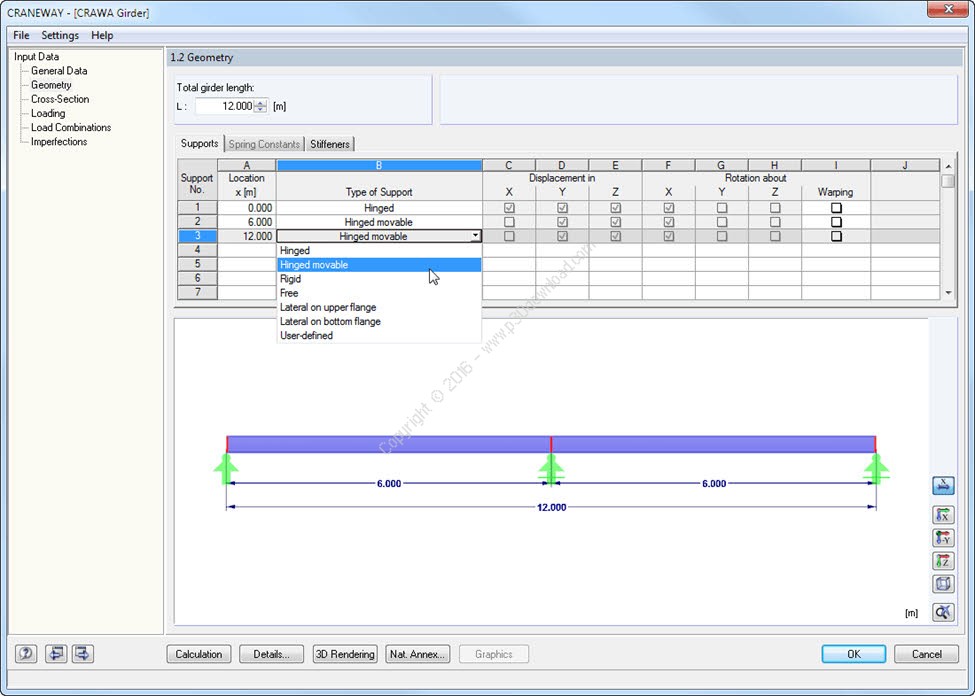
1. Geometry
– Quick and comfortable data input
– Definition of support conditions based on various support types(hinged, hinged movable, rigid, and user-defined as well as lateralon upper or bottom flange).
– Optional selection of warping restraint
– Variable arrangement of rigid and deformable supportstiffeners
– Possibility to insert releases
2. CRANEWAY Cross-Sections
– I-shaped rolled cross-sections (I, IPE, IPEa, IPEo, IPEv, HE-B,HE-A, HE-AA, HL, HE-M, HE, HD, HP, IPB-S, IPB-SB, W, UB, UC, andother cross-sections according to AISC, ARBED, British Steel, Gost,TU, JIS, YB, GB, and others) combinable with section stiffener onthe upper flange (angles or channels) as well as rail (SA, SF) orsplice with user-defined dimensions.
– Unsymmetrical I-sections (type IU) also combinable withstiffeners on the upper flange as well as with rail or splice.
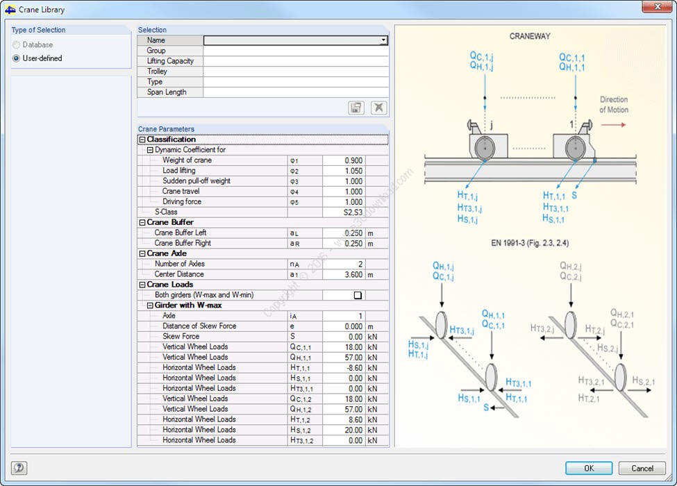
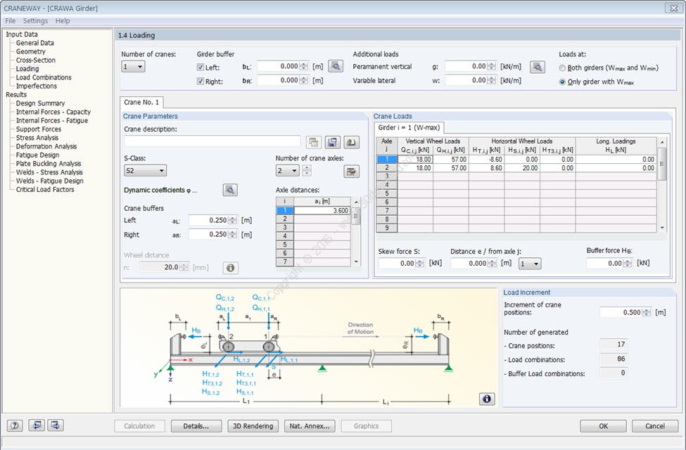
3. Actions
It is possible to consider actions of up to three simultaneouslyoperated cranes. You can simply select a standard crane from thelibrary or define it manually:
– Number of cranes and crane axles (maximum of 20 axles per crane),center distances, position of crane buffers
– Classification in damage classes with editable dynamic factorsaccording to EN 1993-6, and in lifting classes and exposurecategories according to DIN 4132
– Vertical and horizontal wheel loads due to self-weight, liftingcapacity, mass forces from drive as well as skewing
– Axial loading in driving direction as well as buffer forces withuser-defined eccentricities
– Permanent and variable secondary loads with user-definedeccentricities
4. Imperfections
– The imperfection load applies in compliance with the firstnatural vibration mode – either identically for all loadcombinations to be designed or individually for each loadcombination as mode shapes may vary depending on the load.
– Comfortable tools available for scaling the mode shapes (risedetermination of inclination and precamber).
Calculation
During the calculation, crane loads are generated in predefineddistances as load cases of crane runway. The load increment forcranes moving across the crane runway can be set individually.
The program analyzes all combinations of the respective limitstates (ULS, fatigue, deformation, and support forces) for eachcrane position. In addition, there are comprehensive settingoptions for specification of the FE calculation such as length offinite elements or break-off criteria.
The internal forces of a crane runway girder are calculated on animperfect structural model according to the second-order analysisfor torsional buckling.
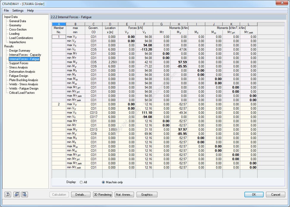
Results
All results are arranged in result windows sorted by differenttopics. The design values are illustrated in the correspondingcross-section graphic. Design details cover all intermediatevalues.
– General Stress Analysis
CRANEWAY performs the general stress analysis of a crane girder bycalculating the existing stresses and comparing them with the limitnormal, shear and equivalent stresses. Welds are also subjected tothe general stress analysis with regard to parallel and verticalshear stresses and their superposition.
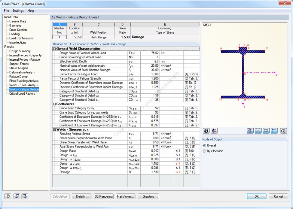
– Fatigue Design
Fatigue design is performed for up to three cranes operating at thesame time, based on the nominal stress concept according to EN1993-1-9. In the case of the fatigue design according to DIN 4132,a stress curve of crane passages is recorded for each stress pointand evaluated according to the Rainflow method.
– Buckling Analysis
Buckling analysis considers the local introduction of wheel loadsaccording to the standard EN 1993-6 or DIN 18800-3.
– Deformation Analysis
Deformation analysis is performed separately for the vertical andhorizontal direction by comparing the designed displacements withthe allowable values. You can individually specify the allowabledeformation ratios in the calculation parameters.
– Lateral-Torsional Buckling Analysis
The torsional-flexural buckling analysis is performed in accordancewith the second-order analysis for torsional buckling consideringimperfections. The general stress analysis has to be fulfilled withthe critical load factor smaller than 1.00. As a result, CRANEWAYdisplays the corresponding critical load factor for all loadcombinations of the stress analysis.
– Support Forces
The program determines all support forces on the basis of thecharacteristic loads including dynamic factors.
Installer Size: 719.2 MB
Download Links : Dlubal CRANEWAY v8.13.01 x64 + Crack